VCC (Virtual Credit Card): Secure Digital Payments Guide 2026
In today’s digital economy, where card-not-present (CNP) fraud continues to challenge online shoppers and businesses, VCC has emerged as a powerful fintech innovation. VCC stands for Virtual Credit Card—a real, widely adopted digital payment tool that enables secure transactions without exposing your primary card details.
As we navigate 2025 into 2026, VCC adoption is accelerating. According to Juniper Research, the global virtual cards market reached $5.2 trillion in 2025, with B2B spending accounting for 76% of that volume. Projections show strong growth, with B2B virtual card payments expected to reach $14.6 trillion by 2029.
This guide explains what VCCs are, how they work technically, who benefits most, and why they represent a smarter approach to payment security and online payments.
Introduction to VCC
Virtual credit cards address a fundamental vulnerability in digital commerce: the risk of sharing your full Primary Account Number (PAN) with every merchant. By creating disposable or controlled digital proxies, VCCs minimize exposure while maintaining full functionality for secure transactions.
Fintech platforms and traditional issuers now generate VCCs instantly via mobile apps or APIs, integrating smoothly with digital wallets like Apple Pay and Google Pay. For freelancers in regions like Faisalabad managing international clients, or businesses handling vendor expenses, VCCs deliver granular control that physical cards simply cannot match.
What Is a Virtual Credit Card (VCC)?
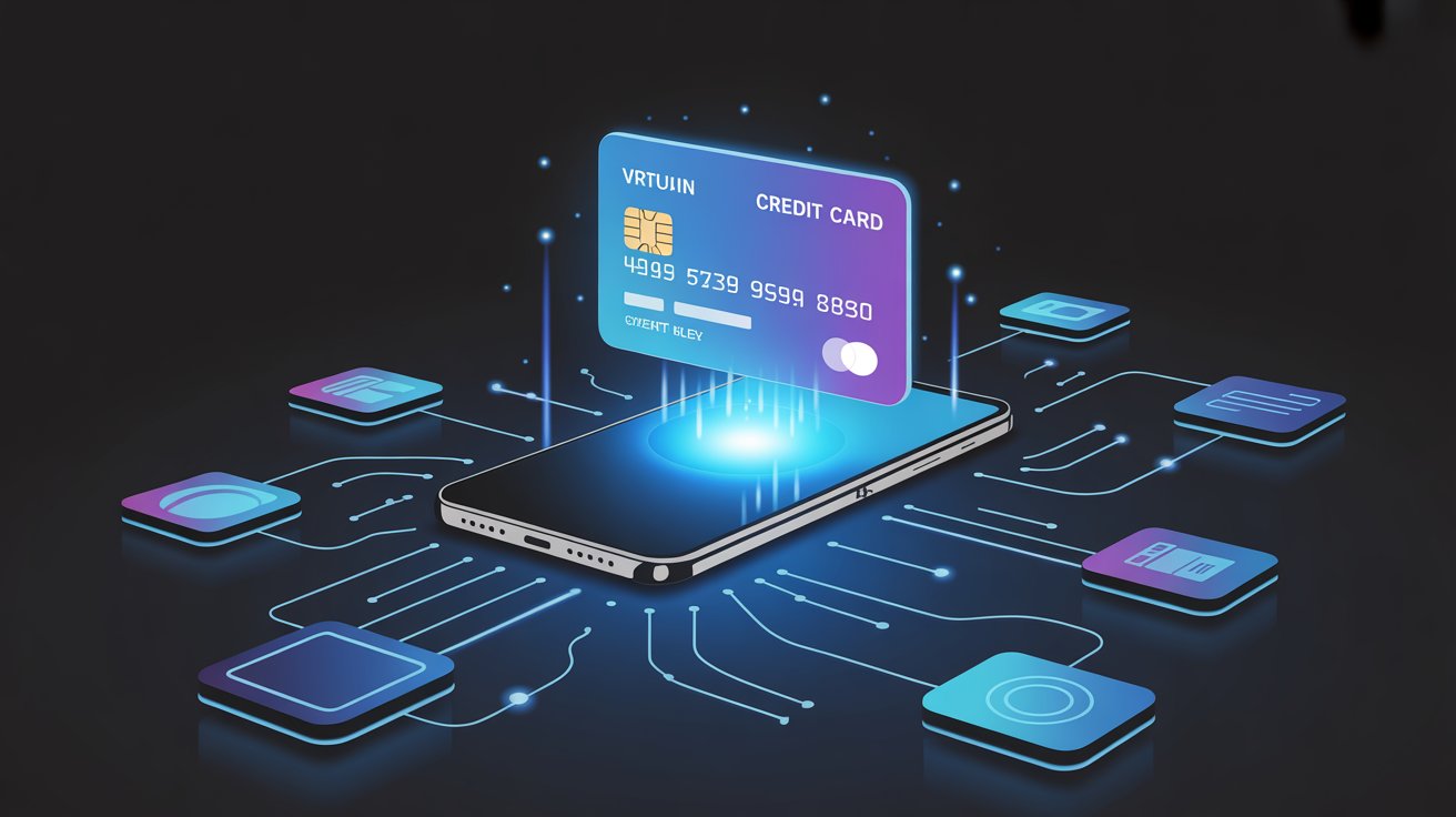
A virtual credit card (VCC) is a digitally generated payment instrument with a 16-digit number, expiration date, and CVV, linked to your underlying credit line or bank account—but existing only in digital form.
Unlike physical cards, VCCs are issued on demand and can be single-use, multi-use with limits, or merchant-restricted. Major providers include Capital One, Citi, Revolut, Wise, and specialized platforms like Airwallex or Marqeta.
Why do VCCs exist? The surge in e-commerce, SaaS subscriptions, and remote work increased card-not-present fraud risks. VCCs act as a protective layer: merchants receive only tokenized or limited-use details, never your real PAN. This directly tackles privacy concerns and reduces the impact of data breaches.
How VCC Technology Works
VCCs rely on payment tokenization, secure APIs, and real-time controls. Here’s the step-by-step technical process:
- Account Linking — Connect your primary credit/debit account to the issuer’s platform.
- Tokenization — The system replaces your sensitive PAN with a unique token via Visa or Mastercard Token Service. The real card data never leaves the issuer’s secure vault.
- Instant Card Generation — Using APIs, the platform creates the virtual card details on demand.
- Spending Rules Configuration — Apply limits, merchant whitelists, time-based expiry, or single-use flags.
- Transaction Authorization — When used, the merchant processes the tokenized VCC. The issuer validates against your rules and maps it back to the real account.
- Post-Transaction Management — Freeze, delete, or monitor the card instantly via dashboard or app.
Payment tokenization is central: Visa reports that nearly 50% of its global e-commerce transactions are now tokenized, significantly reducing fraud while often improving approval rates.
Modern VCC platforms also support open banking standards and embed directly into expense management or ERP systems.
Key Features of VCC Virtual Credit Cards
Leading VCC solutions in 2026 offer:
- Instant issuance with no physical shipping
- Custom per-card spending limits and merchant restrictions
- Single-use or recurring options
- Real-time transaction alerts and dashboards
- API integration for automated workflows
- Compatibility with digital wallets
- Optimized foreign exchange rates for international use
Bold security insight: These controls shift fraud prevention from reactive (disputing charges) to proactive (preventing unauthorized use entirely).
Types of Virtual Credit Cards
- Single-Use VCCs — Perfect for one-time online purchases; auto-expire after transaction.
- Multi-Use/Recurring VCCs — Support subscriptions with spending caps.
- Business/Enterprise VCCs — Bulk issuance with admin controls for teams and vendors.
- Prepaid-Style VCCs — Loaded with a fixed amount for controlled spending.
- Digital Wallet Tokenized VCCs — Optimized for Apple Pay, Google Pay, or in-app payments.
Real-World Applications
Freelancers use VCCs to pay for tools like Upwork, Adobe, or hosting services while limiting exposure. One common insight from users: switching to VCCs for recurring subscriptions often reduces unauthorized charges dramatically.
Businesses deploy them for expense management, supplier payments, and ad spend. Travel agencies and OTAs issue controlled VCCs to hotels with embedded limits. In B2B, virtual cards streamline procurement and reduce reliance on slower wire transfers.
Benefits of Using VCC
- Stronger fraud protection — Delete a compromised card instantly.
- Enhanced privacy — Merchants never see your real PAN.
- Better spending discipline through automated limits.
- Faster issuance and management.
- Reduced chargeback costs for merchants.
- Improved tracking and reporting for businesses.
- Seamless international online payments.
Limitations and Risks of VCC
VCCs excel in digital scenarios but have constraints:
- Primarily online-focused (though some integrate with digital wallets for contactless).
- Occasional merchant acceptance issues with strict processors.
- Still tied to your underlying credit line.
- Potential small fees on some platforms.
- Requires understanding controls to avoid unexpected declines.
Risks remain low when using reputable issuers, but always avoid sharing details via unsolicited channels. PCI compliance is typically handled by the issuer, easing the burden on users and businesses.
VCC vs Physical Credit Cards
| Aspect | VCC (Virtual Credit Card) | Physical Credit Card |
|---|---|---|
| Form | Digital, instant generation | Physical plastic |
| Security | Tokenization + disposable controls | Chip/PIN + standard alerts |
| Fraud Risk (CNP) | Significantly lower | Higher if details are breached |
| Spending Control | Granular per-card rules | Broad credit limit only |
| Best Use Case | Online payments, subscriptions, B2B | In-store, ATM, everyday use |
| Replacement | Instant delete & regenerate | Days to receive new card |
| Digital Wallet Fit | Native with extra token layers | Manual addition |
Security and Fraud Protection with VCC
Security remains the standout advantage of VCC technology. Tokenization ensures stolen virtual details have limited or no value. Combined with AI-driven monitoring, 3D Secure, and biometric prompts, VCCs create multiple defensive layers.
Visa data shows tokenization can reduce fraud by around 35% in many e-commerce scenarios while boosting legitimate sales. For businesses, VCCs simplify PCI compliance and provide clear audit trails.
Bold key security insight: In an era of rising card-not-present fraud, VCCs limit damage by design—your main account stays protected even if one virtual card is exposed.
Future of Digital Payments and VCC
By 2026–2029, VCCs will integrate deeper with AI agents, embedded finance, and real-time payment rails. Expect more “agentic” commerce where AI handles purchases within strict VCC rules, plus convergence with stablecoins and tokenized deposits.
Juniper Research and industry analysts see virtual cards as one of the fastest-growing B2B payment methods, driven by security needs and operational efficiency. The broader shift toward payment tokenization and secure online checkout will make VCCs even more central to fintech solutions.
FAQ
What is a VCC? A VCC (Virtual Credit Card) is a digital-only payment card generated instantly for secure online transactions, linked to your main account but without exposing your real card details.
Is a VCC safe? Yes. Advanced tokenization, spending controls, and instant cancellation make VCCs one of the safest options for digital payments.
How do I get a virtual credit card? Most banks and fintech apps (Capital One, Revolut, Wise, etc.) allow instant generation after linking your account via their mobile app or dashboard.
Can VCC be used internationally? Yes, most support global online merchants and often provide competitive FX rates for cross-border payments.
Who should use VCC? Freelancers, online shoppers, businesses managing expenses or supplier payments, and anyone seeking stronger fraud protection and control.
Are there any risks with VCC? Risks are minimal compared to traditional cards, mainly related to user error or choosing unreliable providers. Stick to established issuers.
What is the future of virtual payments? Strong growth through AI integration, deeper tokenization, and seamless embedding into digital wallets and business software, making secure transactions even more frictionless by 2030.
Conclusion
VCC (Virtual Credit Card) technology has become a cornerstone of modern fintech solutions and payment security. By combining instant issuance, powerful controls, and robust tokenization, VCCs solve real problems around fraud, privacy, and expense management in 2025–2026.
Whether you’re a freelancer protecting client-related payments, a business optimizing vendor spend, or simply an online shopper wanting peace of mind, adopting VCCs is a practical step toward safer digital finances.
Recommendation: Start with a reputable bank or fintech provider that supports virtual cards. Generate your first VCC for your next subscription or online purchase and experience the difference in control and security.
Share this content:


Post Comment